
Any time a part is ordered to be manufactured, every feature is subject variation from the designed value. The maximum allowable variation is described as tolerances – which are particularly important when many copies of the same part must be made and fit together with many other complementary parts. GD&T, or Geometric Dimensioning and Tolerancing, is an approach to describing engineering intent of parts and assemblies when ordering which allows for over 50% more tolerance than linear (coordinate) dimensioning – while still insuring the part can perform as intended. Inherently, this means parts can be made at lower cost (due to more wiggle room) for the same quality.
GD&T is often seen on a print as an addition block featuring symbols and values associated with those symbols. Common symbols are listed in the table below, but the go-to reference for GD&T symbols is ASME Y14.5 Dimensioning and Tolerancing (among other fabulous standards).
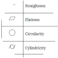
| Symbol | Name | Type of Control | Datum Use |
| Straighness | Form | No | |
| Flatness | Form | No | |
| Circularity | Form | No | |
| Cylindricity | Form | No | |
| Line Profile | Profile | Sometimes | |
| Surface Profile | Profile | Sometimes | |
| Perpendicularity | Orientation | Yes | |
| Angularity | Orientation | Yes | |
| Parallelism | Orientation | Yes | |
| Symmetry | Location | Yes | |
| Position | Location | Yes | |
| Concentricity | Location | Yes | |
| Circular Run-out | Run-Out | Yes | |
| Total Run-out | Run-Out | Yes |
Some symbols are independent of a reference frame, or datum, such as Straightness, Flatness, Circularity or Cylindricity. However, most symbols rely on the indicated datum to describe relevant dimensions or even what order to measure if parts are conforming.
Datums are described using a symbol with a reference letter aligned to a measurement or a feature. If the label is aligned to the center of a measurement, the datum is actually the centerline of the measurement, rather than the side of measurement that the datum is attached to.

Further, a feature control frame can impart conditional preferences with context to how the part will be used in relation to other parts.
| Symbol | Modifier | Description |
| Free State | Avoids Over-constraining the Part | |
| Maximum Material Condition (MMC) | Used to ensure parts at “maximum” tolerance size do not overlap | |
| Least Material Condition (LMC) | Used to ensure parts at “maximum” tolerance size do not have too much wiggle room | |
| Projected Tolerance Zone | Useful for threaded holes for long studs | |
| Regardless of Feature Size (RFS) | Default setting, does not need to be called out. No considerations for part overlap or excess space between components. | |
| Tangent Plane | Interfaces where form is not required |
GD&T Controls often appear within a block referencing a feature as shown below. The symbol indicates the type of geometric characteristic, a value, and the order in which the feature’s compliance is assessed.
